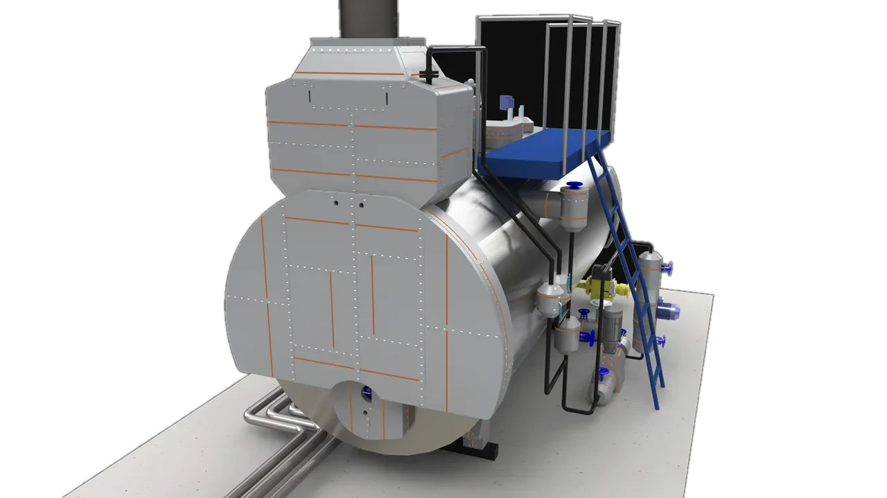
A boiler mounting is a fitting required on the pressure vessel itself before it can be operated. Six of them stand on this view. From the rear quarter the live-steam fittings come into view — check and main stop valves, the safety valves, the rear manhole, steam flanges and sensor flanges. These all sit at the boiler’s saturation temperature, about 180 °C, bare.
Figures are for one boiler. Surface temperatures from a real FLIR survey of a UK commercial boiler house; CAD surface areas uplifted ×1.4 for bolts and irregular geometry; ISO 12241 steady-state (50 mm core, ambient 28 °C, air movement 0.5 m/s).


Drag-free toggle. Visible in this view: check & main valves, safety valves x2, rear manhole, steam flanges and sensor flanges — all ~180 °C, bare cast bodies.3D model: Inzonex · equipment rights belong to the manufacturer
Valves and flanges are the surfaces insulation contractors skip most often, because their irregular cast shapes don’t suit rigid boxes — yet they run at the hottest temperature on the boiler, the saturated-steam ~180 °C.
Per unit area a bare valve loses more than a flat plate at the same temperature, and there are several of them. Tailored two-part removable covers insulate the body and seats while leaving the spindle and gland serviceable.
| Element (this view) | Temp °C | Area m² | Bare W | Insulated W | Surface °C | Cut |
|---|---|---|---|---|---|---|
| Check (non-return) valve | 180 | 0.90 | 2,599 | 131 | 39 | −95% |
| Main stop valve | 180 | 0.60 | 1,732 | 87 | 39 | −95% |
| Safety valves ×2 | 180 | 0.68 | 1,963 | 99 | 39 | −95% |
| Manhole | 180 | 0.39 | 1,126 | 57 | 39 | −95% |
| Steam flanges ×2 | 180 | 0.34 | 982 | 49 | 39 | −95% |
| Sensor flanges ×2 | 180 | 0.24 | 693 | 35 | 39 | −95% |
| Rear three-quarter view view, per boiler | 3.1 | 9,095 | 458 | ≤45 | −95% |
ISO 12241, 50 mm Inzonex modular core, ε(bare)=0.9, ε(jacket)=0.85, hconv at 0.5 m/s. Insulated figures are conservative steady-state.
On the feed/steam line at ~180 °C with an irregular cast body that no rigid box fits. A tailored two-part removable cover insulates the bonnet and seats while leaving the spindle serviceable.
Cover: Silicone shell + PAROC stone-wool core (50 mm) · touch-safe design target ≤45 °C (ISO 13732-1 guidance)
The main steam take-off valve runs at full saturation temperature. Its flanges and bonnet are a concentrated loss; a removable jacket cuts it ~95% and stays off the gland.
Cover: Silicone shell + PAROC stone-wool core (50 mm) · touch-safe design target ≤45 °C (ISO 13732-1 guidance)
Safety valves must stay free to lift and discharge — so the seat and outlet are never covered. But the valve body and the run of pipe up to it sit at ~180 °C and can be insulated, with the lift mechanism and drain left clear. That is the difference between a fixed box and a shaped removable panel.
Cover: Silicone shell + PAROC stone-wool core (50 mm) · touch-safe design target ≤45 °C (ISO 13732-1 guidance)
Small but among the hottest points, and it must come off for internal inspection. Rigid insulation gets cut away at the first service and never returns. A buttoned panel unclips and re-fits, so it survives maintenance.
Cover: Silicone shell + PAROC stone-wool core (50 mm) · touch-safe design target ≤45 °C (ISO 13732-1 guidance)
Bolted steam-line flanges are routinely left bare for “leak checking”, then forgotten. Removable flange shrouds insulate them yet pop off in seconds for inspection.
Cover: Silicone shell + PAROC stone-wool core (50 mm) · touch-safe design target ≤45 °C (ISO 13732-1 guidance)
Instrument flanges for level and pressure sensors sit on the steam side at ~180 °C. Each is a small bare hot-spot that must stay accessible; a shaped removable cover insulates the flange without burying the instrument.
Cover: Silicone shell + PAROC stone-wool core (50 mm) · touch-safe design target ≤45 °C (ISO 13732-1 guidance)
Every module here re-opens for access.
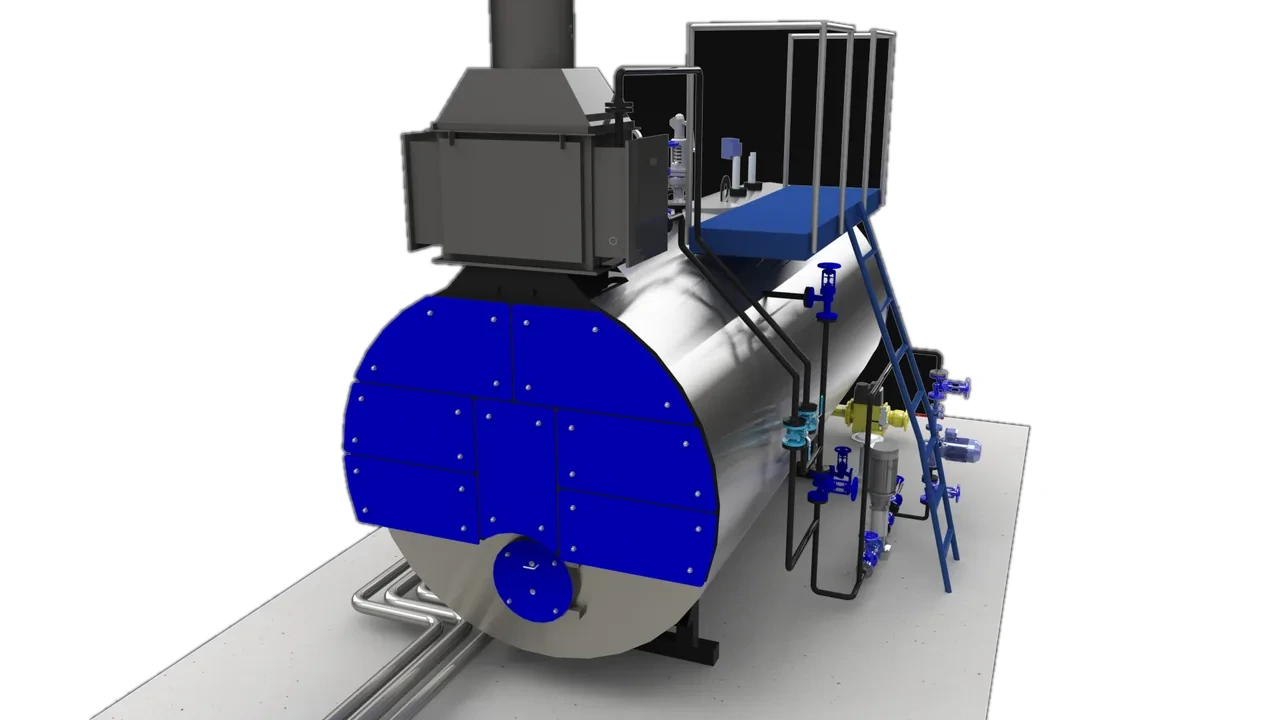
Every surface on this view is covered by an Inzonex modular removable panel: a PAROC stone-wool core (50 mm) in a silicone outer shell — or a more durable PTFE shell as an option. The form-fitting build unbuttons for access and refits after each maintenance cycle. The outer surface drops to a touch-safe ≤45 °C.
Industries that run this boiler
Put in your boiler count, fuel price and running hours — get energy, £ and payback for the whole room.
Open calculator → CarbonEvery bare kilowatt is real fuel and real carbon. See the tonnes and the EU-ETS cost behind it.
Carbon hub → 3D modelRotate the Cochran model, toggle bare vs insulated, and jump to every other surveyed surface.
Open 3D model →On the surveyed Cochran the main stop, check and feed valves measured ~180 °C bare — the saturated-steam temperature of the boiler.
Yes — with removable two-part covers shaped to the body. They cut ~95% of the loss yet pull off in seconds for inspection, unlike rigid lagging that has to be destroyed to service the valve.
Their cast shape doesn’t fit rigid cladding and they need periodic access, so contractors skip them — leaving the hottest points on the boiler uninsulated.
Selected readings from this boiler survey. This surface is the marked point.
Saturated steam has one temperature for each pressure. That is why a valve body runs hot: it is held near the temperature of the steam passing through it, and that temperature is set by the pressure in the line, not by the burner.
| Gauge pressure, bar | Absolute, bar | Saturation temperature |
|---|---|---|
| 0 | 1.013 | 100.0 |
| 1 | 2.013 | 120.2 |
| 2 | 3.013 | 133.5 |
| 3 | 4.013 | 143.6 |
| 4 | 5.013 | 151.8 |
| 5 | 6.013 | 158.8 |
| 6 | 7.013 | 164.9 |
| 7 | 8.013 | 170.4 |
| 8 | 9.013 | 175.4 |
| 9 | 10.013 | 179.9 |
| 10 | 11.013 | 184.1 |
| 12 | 13.013 | 191.6 |
| 14 | 15.013 | 198.3 |
The rear valve and steam set on this page reads 180 °C on the outside. Saturated steam is at 179.9 °C when the line is at 9 bar gauge, so a body at this surface temperature is running close to line temperature — the metal has almost nothing between it and the steam.
Saturation temperatures are standard physical data for water and steam, not our measurement. What we measured is the surface: a thermal camera reads the outside of the body, which sits at or below the temperature of the steam inside it. Absolute pressure is gauge plus 1.013 bar.
Every figure on this page comes from the same chain: a radiometric camera reading of the surface, an area rebuilt in CAD from the surveyed machine, and an ISO 12241 calculation from those two. The instrument settings, the area allowance, the energy basis and the list of what was not measured are set out once, in full, on the method page.
| Survey | Cochran, rear three-quarter view. FLIR S62 Pro, emissivity 0.90, reflected 25 °C, 3 m, full radiometric correction. Peak on this view 180 °C. |
| Geometry | Rebuilt in CAD from the surveyed machine. This view carries 6 element group(s) and sheds 9.1 kW bare. The ×1.4 factor is a geometry allowance for bolts, seams and irregular surface — it is not a measured area. |
| Calculation | ISO 12241 steady state. Heat loss is calculated from the measured surface temperature and the modelled area — it is not metered. Full method, basis and limits. |
| Largest single item | Check (non-return) valve, 2.6 kW on this view. |
| Regulation | The Pressure Systems Safety Regulations 2000 · HSE L122, Safety of pressure systems · HSE INDG261, Pressure systems |
On a working Cochran package boiler the rear end plate and the economizer behind it run at 126–130 °C — FLIR-measured, bare. Together they are the sin…Open the measured page
→/ 02The feed and condensate side runs near 100 °C across the pump, isolation valves, return lines, strainer and blowdown — many small bare surfaces that q…Open the measured page
→/ 03The front door carries the burner and closes onto the furnace tube behind it — a 5.3 m² face at about 120 °C bare. It also has to hinge open for burn…Open the measured page
→