02 / BEFORE AND AFTER
The same three surfaces, measured twice
Steam valves
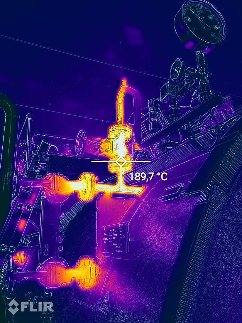
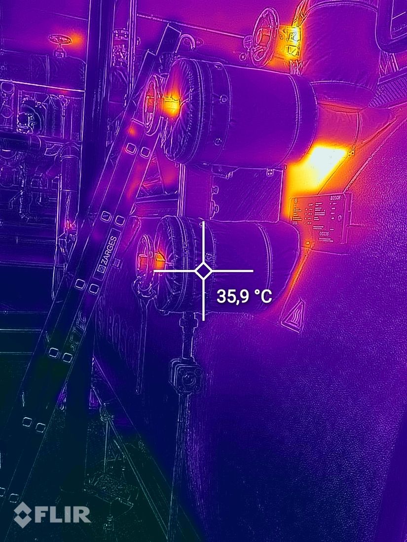
Before 190 °CAfter 36 °C
Boiler door
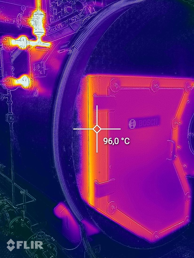
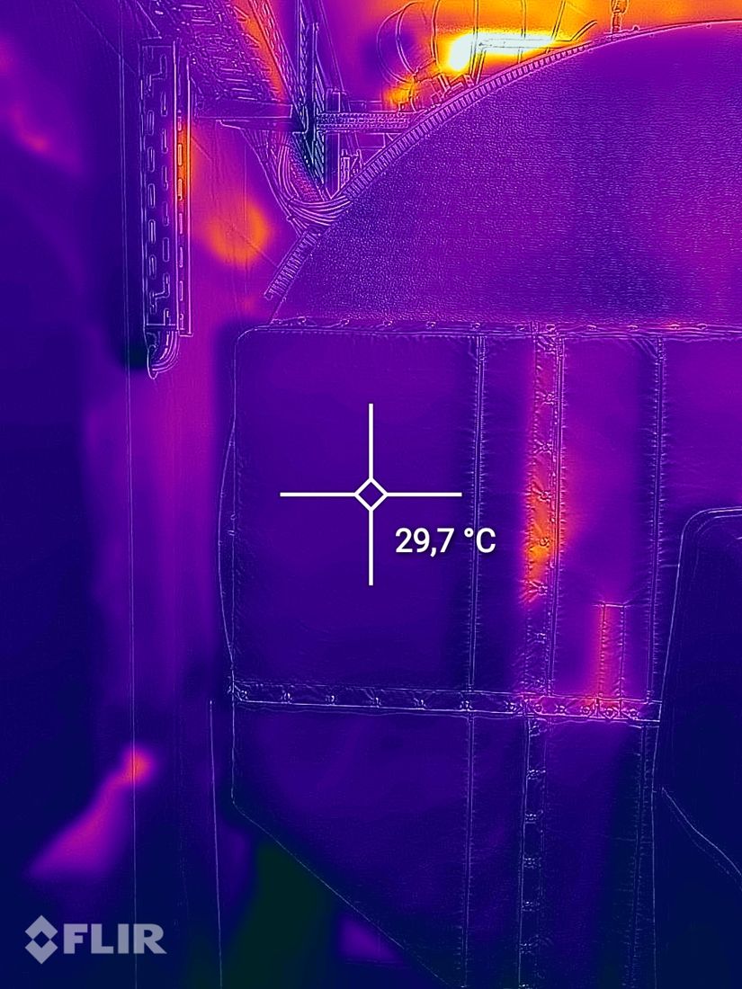
Before 96 °CAfter 30 °C
Burner flange
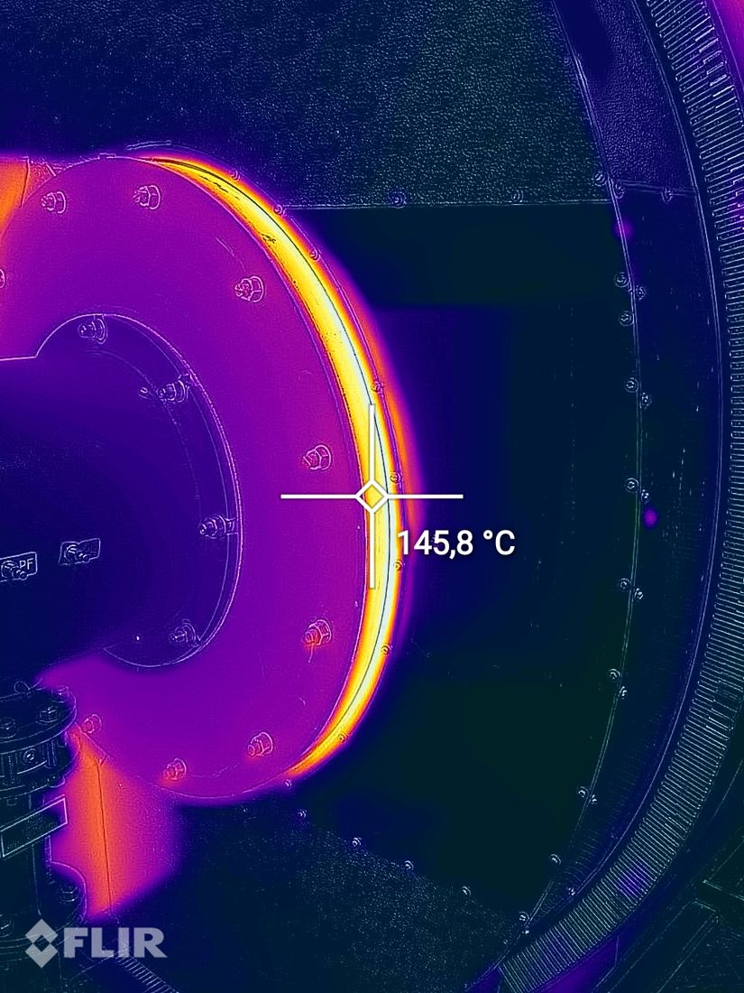
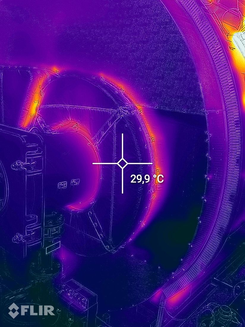
Before 146 °CAfter 30 °C
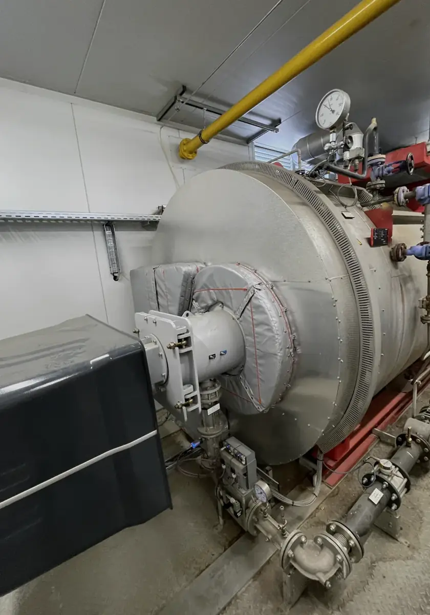
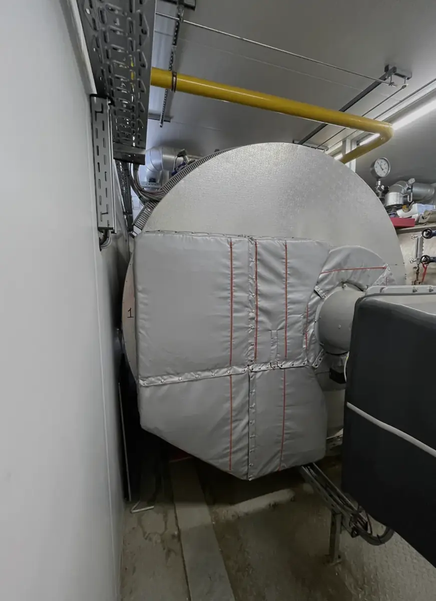
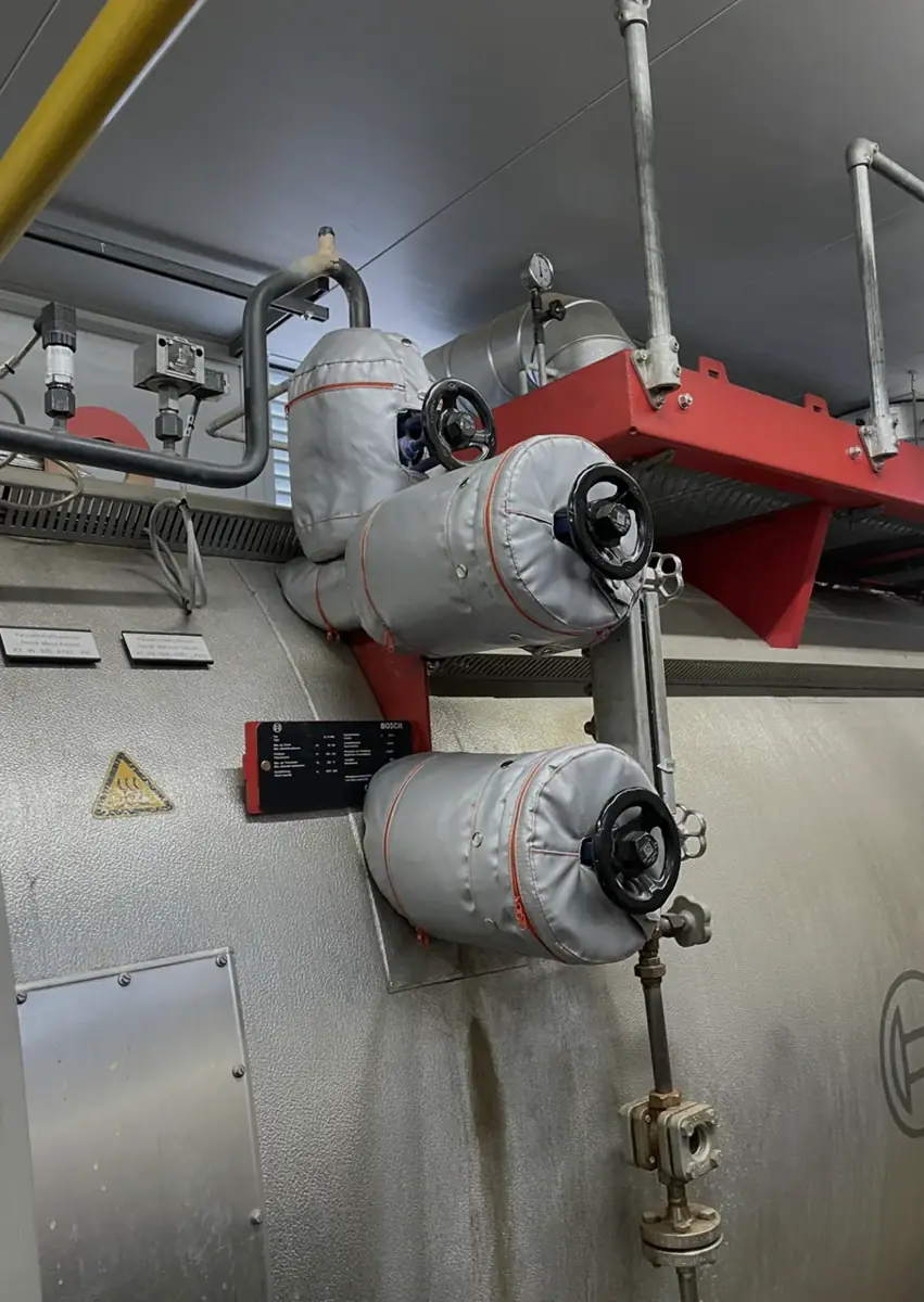
A Bosch steam boiler insulated end to end: door, burner flange and steam valves. The hottest bare surface read 190 °C on the camera; under panels the same surface reads 30 to 36 °C, inside the 45 °C touch-safe design target, assessed to EN ISO 13732-1.
Across the boiler room, 35 of 38 infrared frames showed exposed hot metal above 60 °C. They are the components rigid cladding and metal boxes leave open: valve bodies, flanges, the boiler door and the burner connection. Bare valves and steam lines up to 190 °C were putting that heat straight into the room.
| What the survey saw | Reading |
|---|---|
| Exposed and radiating | Bare valves and steam lines up to 190 °C, into the plant room |
| Touch risk | Uninsulated metal far above the 45 °C design target, assessed to ISO 13732-1, at working height |
| First step | Audit and panel the bare spots; each panel comes off in minutes for service |
| Location | Bare, before | Panelled, after | Drop | Reduction |
|---|---|---|---|---|
| Steam valves | 190 °C | 36 °C | 154 °C | 93 % |
| Bosch boiler door | 96 °C | 30 °C | 66 °C | 93 % |
| Burner flange | 146 °C | 30 °C | 116 °C | 96 % |
| Location, bare face | C680 ideal panel, 100 mm | FLIR measured | Note |
|---|---|---|---|
| Bosch boiler door, 96 °C | 28 °C | 30 °C | continuous panel close to model, warmer at seams |
| Burner flange, 146 °C | 30 °C | 30 °C | continuous panel, model and reading agree |
| Steam valves, 190 °C | 32 °C | 36 °C | stems left exposed for service |
| Removable element | CAD area | +12 % surface | Surface bare → panel | Heat loss bare → panel | Saved MWh/yr | €/yr | CO₂ t/yr |
|---|---|---|---|---|---|---|---|
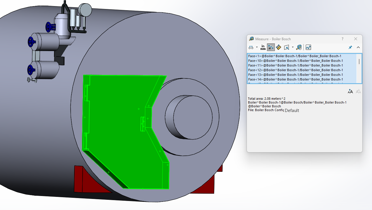
| Front door | 2.08 m² | 2.33 m² | 96 → 30 °C | 2.53 → 0.15 kW | 21.5 | €1,289 | 4.30 |
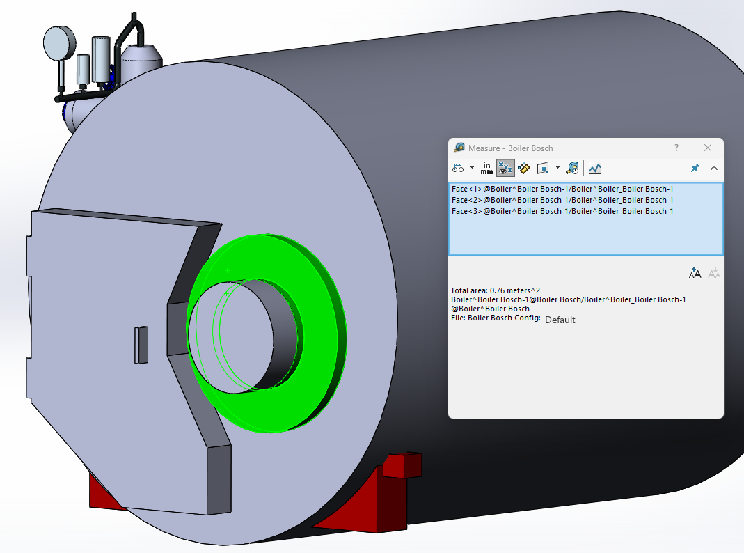
| Burner flange | 0.76 m² | 0.85 m² | 146 → 30 °C | 1.78 → 0.06 kW | 15.6 | €937 | 3.12 |
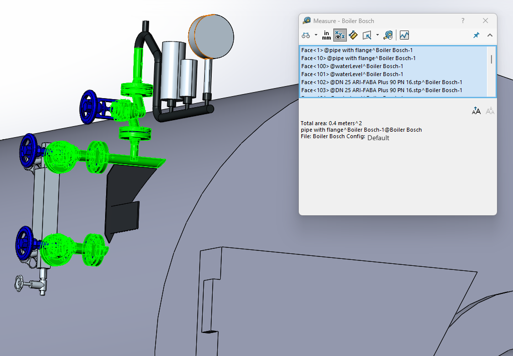
| Steam valves | 0.40 m² | 0.45 m² | 190 → 36 °C | 1.43 → 0.07 kW | 12.4 | €743 | 2.48 |
| Three access elements, subtotal | 3.24 m² | 3.63 m² | −95.2 % | 5.74 → 0.28 kW | 49.5 | €2,970 | 9.9 |
| Whole boiler, 12 element types, 28 pieces | — | — | — | 23.4 → 1.2 kW | 171 | €12,083 | 40.3 |
The three surfaces above are what the camera quantified directly. The 23.4 kW is the full element set: it also carries the economiser, the feed and condensate lines and the pump. At 7,700 h/yr the whole machine keeps 171 MWh of heat in the boiler, which is 201 MWh of gas at 85 % boiler efficiency, €12,083 at 60 €/MWh and 40.3 t of CO₂ at 0.20 kg/kWh.
The band at the top of this page is that whole-boiler figure, for one 6-ton boiler.
Camera spot markers, FLIR S62 Pro with full radiometric correction, 13 October 2025. Surface heat-loss reduction is 1 − (T panel − T ambient) / (T bare − T ambient).
Measurement. Radiometric infrared with a FLIR S62 Pro: emissivity 0.90, reflected 25 °C, atmospheric 25 °C, 50 % relative humidity, 3 m. Temperatures are recomputed per pixel from the raw thermal matrix embedded in each file together with its Planck constants, with exiftool and raw2temp; full-field values agree with the camera spot markers to about 1 °C. Camera accuracy ±2 °C or ±2 %. ISO 18434-1, ASTM E1933.
Model. Steady state to ISO 12241 and ASTM C680, convection at 0.5 m/s with radiation stated separately.
Area. Each component is rebuilt in CAD from the surveyed machine and its outer surface area is read off the model. A 12 % allowance is added for bolts, nuts, weld seams and surface irregularity, because those enlarge the real radiating and convecting area.
Cutting 93 to 96 per cent of the surface loss removes most of the equipment heat load on the room air. With ventilation unchanged, the excess temperature of the room falls roughly in proportion.
| Room excess before | Retained heat, 100 mm | Estimated after | Approximate drop |
|---|---|---|---|
| +8 °C | ~4 % | ~+1.4 °C | ~6–7 °C cooler |
| +12 °C | ~4 % | ~+2.1 °C | ~10 °C cooler |
| +15 °C | ~4 % | ~+2.6 °C | ~12 °C cooler |
This one is an estimate, not a measurement. Room excess before was +8 °C; paired room-air readings after the work were not taken on this site, so no measured figure is published for it. The measured 8 °C drop we do publish comes from the Cochran laundry case, where the six-point grid was read twice.
The same removable panel applies unchanged to bigger boilers: doors, the valves on top of the shell and the hot saddle supports are each panelled and stay removable for service.
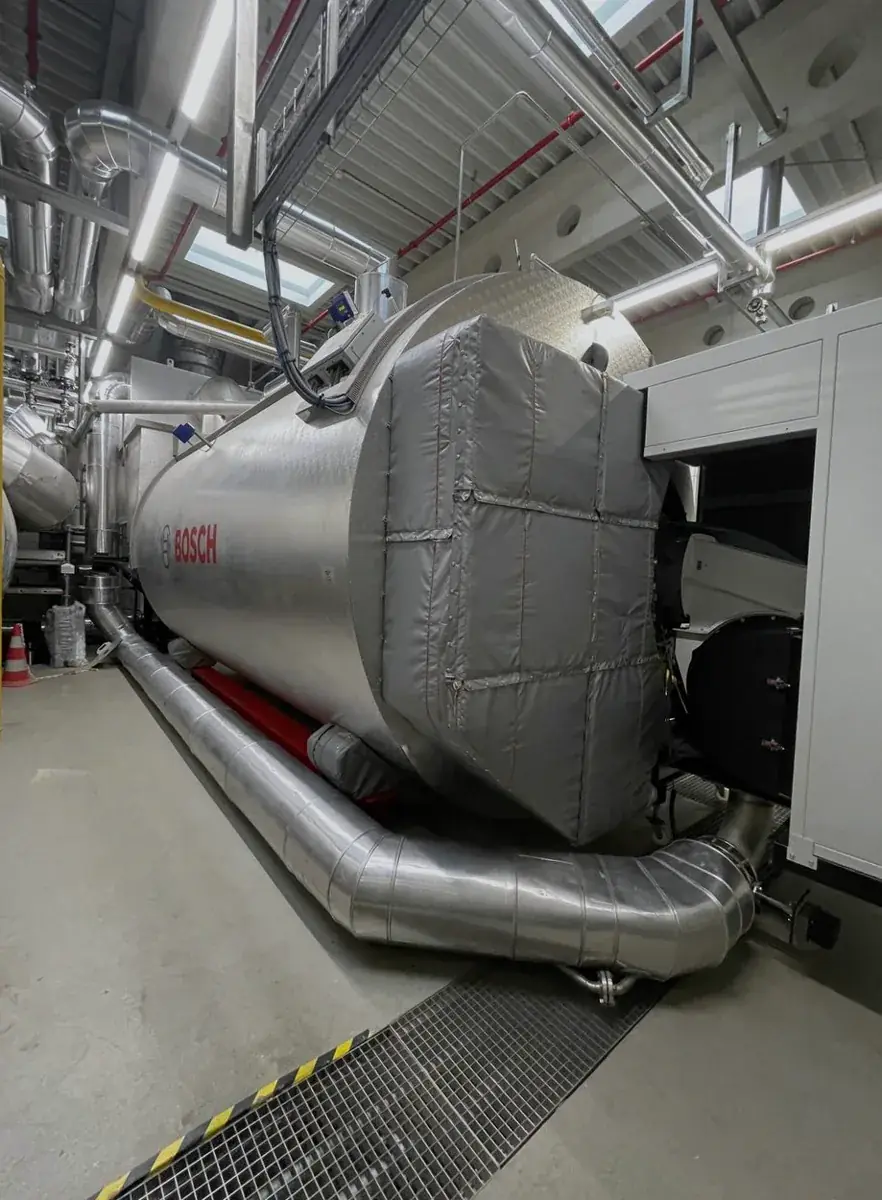
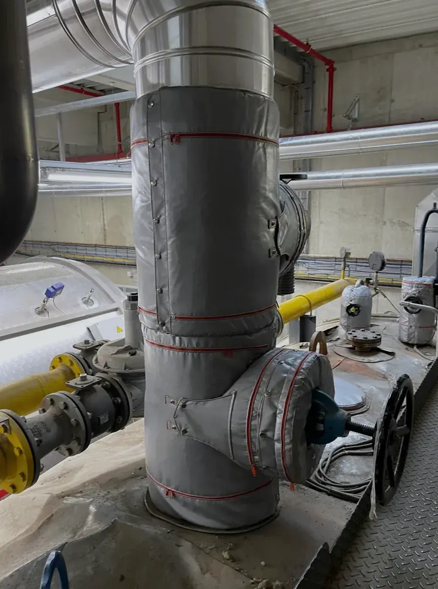
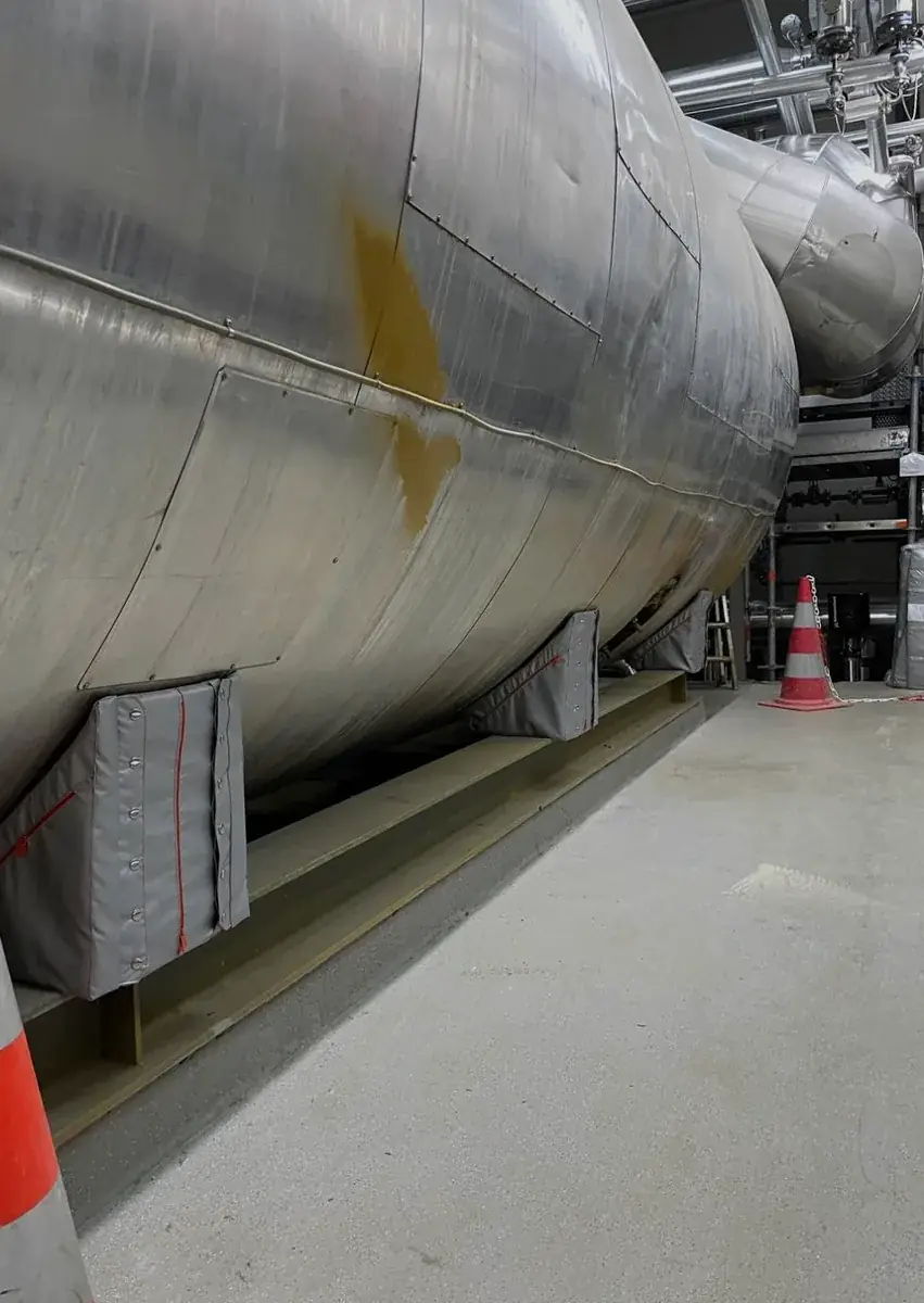
Data availability. Surface-temperature dataset and data descriptor, CC BY 4.0 — doi.org/10.5281/zenodo.20832589. Preprint: engrXiv DOI 10.31224/7444. Method: ASTM C680, ISO 12241, ISO 18434-1, ASTM E1933. Instrument: FLIR S62 Pro, ±2 °C.
The steam valves read 190 °C, the boiler door 96 °C and the burner flange 146 °C, taken with a FLIR S62 Pro at emissivity 0.90 and 3 m.
Steam valves 36 °C, boiler door 30 °C, burner flange 30 °C. All three sit inside the 45 °C touch-safe design target, assessed to EN ISO 13732-1.
93 per cent on the valves and the door, 96 per cent on the burner flange, by 1 minus the ratio of panelled to bare excess over ambient.
Yes. Every panel is removable by hand: the door swings, the valve hand-wheels are left clear and instruments stay outside the covered area.
Each component was rebuilt in CAD from the surveyed machine and its outer area read off the model, with 12 per cent added for bolts, nuts, weld seams and surface irregularity.
On this site paired room-air readings were not taken, so no measured figure is published for it. The measured 8 °C drop we do publish comes from the Cochran laundry case.
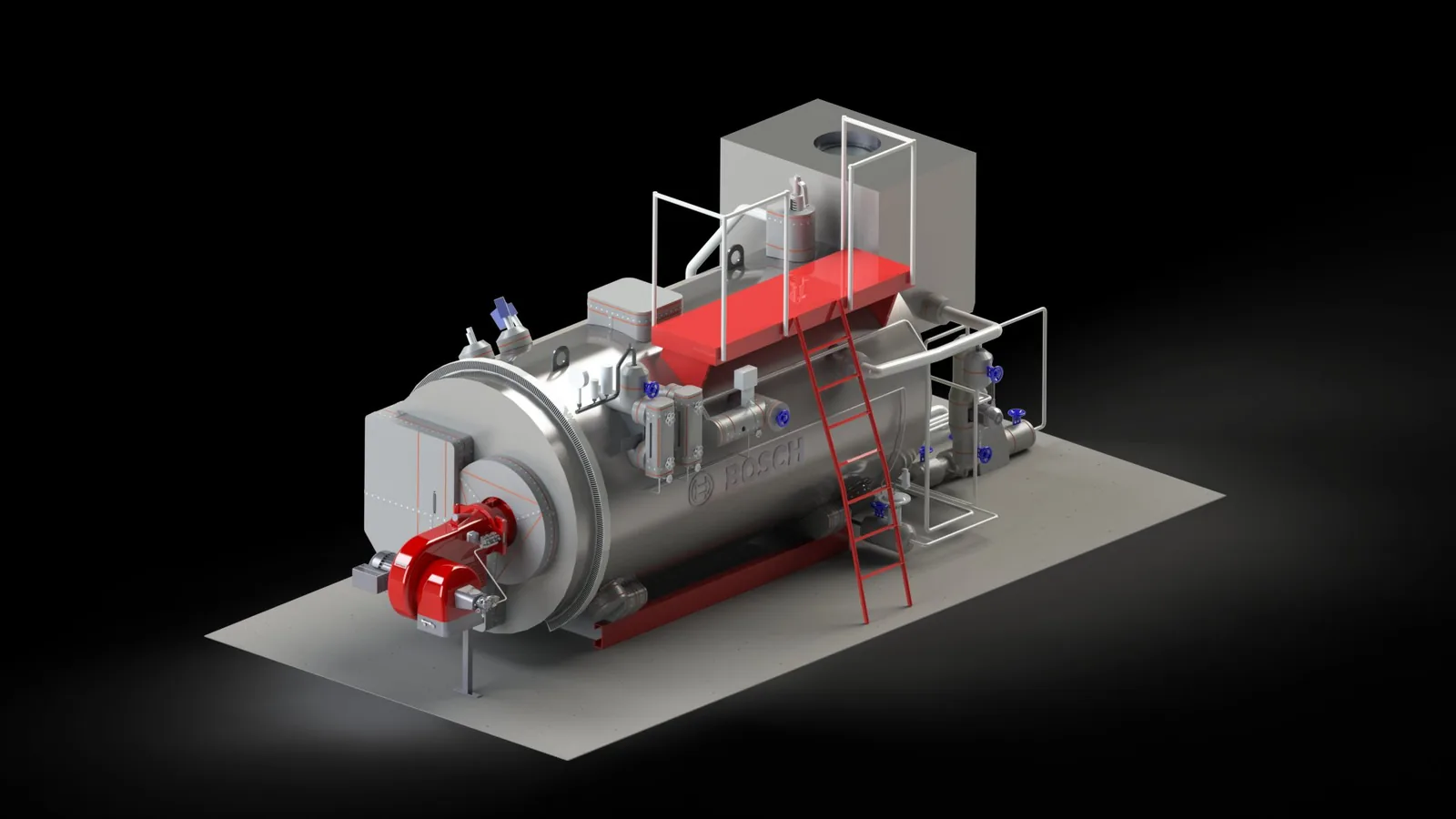
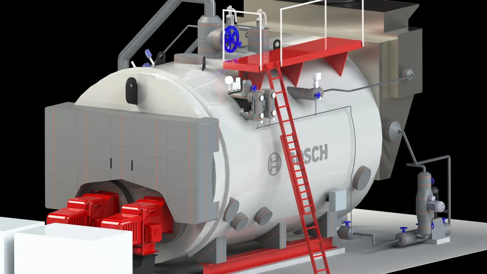
Both models are built by hand in CAD from a field survey, and both carry the same before-and-after readings as this page. The ZFR is the larger twin-furnace machine: 53.4 kW bare against 4.0 kW panelled.
Tell us the setup and we prepare an infrared survey plan, an ASTM C680 saving estimate and a removable-panel proposal with payback.
Study preparation takes 7–10 days once we have the required photos and equipment data. Details are used only to prepare the assessment.