support flange and metal bellows combined
Upper HP line · project-derived geometry
Support flange with metal bellows
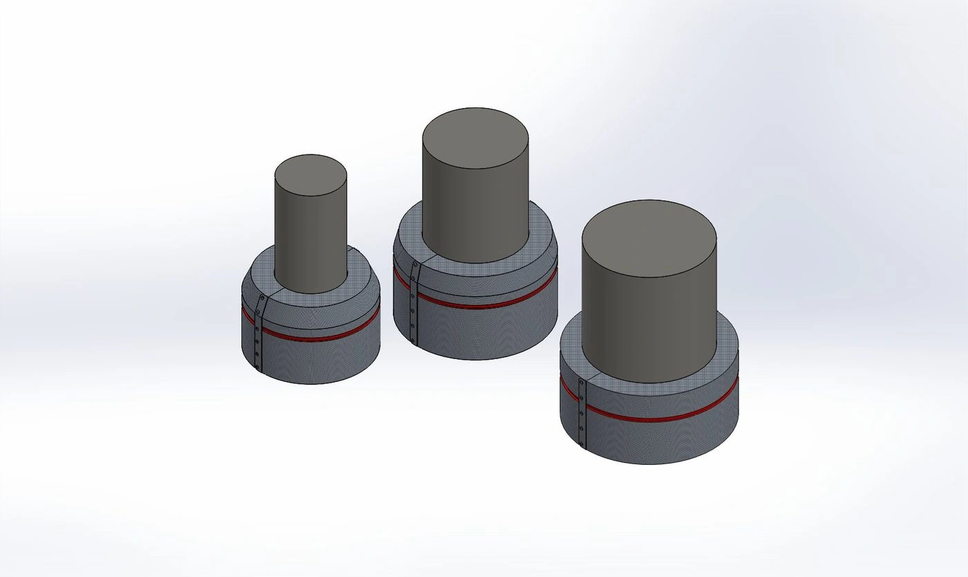
The insulation covers the HP line support flange and the metal bellows directly below it. Three before-and-after views show the corrugation, support clearance and removable module.
Reference temperature 460 °C45 mm pitch · 18 mm depthWired Mat 100 mm basisOuter model 40.8 °C
planning residual for the combined detail
per combined detail at the reference temperature
modelled result · ≤45 °C target met
Normal and thermal views
One HP line detail, three useful views
Drag the divider to compare the bare support flange and metal bellows against the removable module. Use the Normal / Thermal control inside each view.
3D perspective
Support flange and metal bellows
Corrugation, support clearance and the external removable module.
Open normal / thermal →Technical front
Single HP line detail
Front elevation and thermal comparison of the same support flange and metal bellows.
Open normal / thermal →Repeated row
Installation pattern
How the removable modules repeat across a representative row.
Open normal / thermal →What the visual shows
Insulated parts and calculation limits
The render shows the metal bellows, support flange, removable module and access for inspection. Thermal figures come from the calculation, not from image colour alone.
Heat and outside surfaceConvection and radiation use the project-derived geometry and reference duty.
Inspection accessThe module can be removed so the support flange and metal bellows can be inspected and covered again.
Equipment conditionKeeping the parts insulated reduces heat exposure, but no fixed service-life extension is claimed without condition and operating-history data.
Commercial valueGas price, project cost and payback stay blank until the operator enters them.
Calculate your savings
Adjust temperature, number of similar elements, operating hours and your own commercial rates.